Nested Bioretention
Bioretention basins may be designed to manage a site’s Water Quality (WQv), Channel Protection (CPv), and 2yr-24 hour and 100yr-24 hour Flood Detention (Qp) requirements. This is accomplished by nesting the WQv, CPv, and Qp volumes within a single basin.
This concept may be applied to both new and redevelopment sites of any size, however as a general guide, the maximum watershed acreage tributary to a nested bioretention cell should be limited to five acres. This is to preserve the life cycle and performance of the filter media and vegetation; and to ensure for reasonable maintenance expectations for the end user. Certain circumstances may warrant a larger tributary area (such as natural resources preservation, the application of other volume reducing water quality strategies within the basin’s tributary watershed) and will be considered by MSD on a case by case basis.

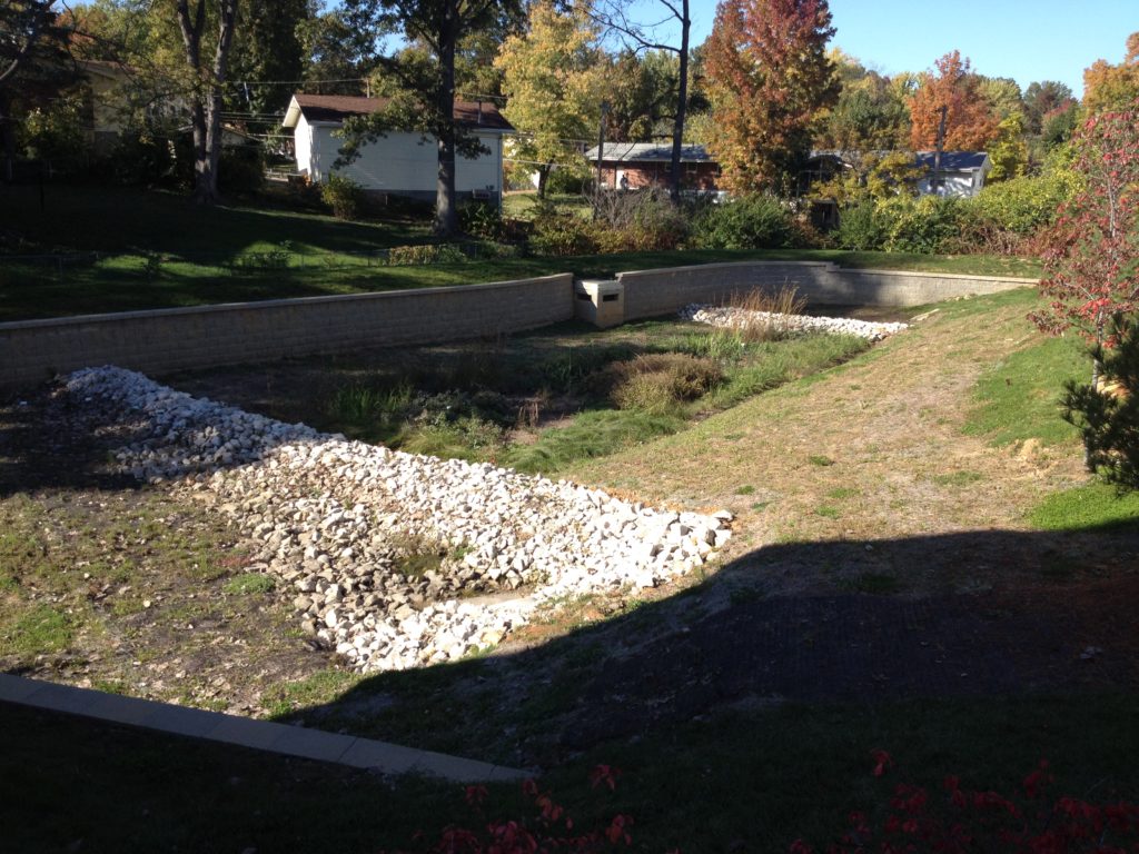
Figure 1: Boswell Place, MSD P-29388-00

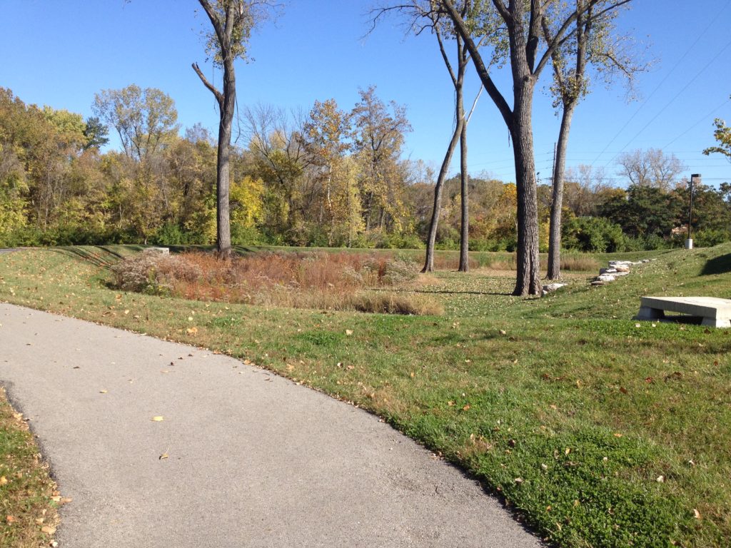
Figure 2: Sherbrooke Village, MSD P-15458-04
Components
Nested Bioretention Basins consist of three zones: Pre-treatment, transition, and treatment.
The characteristics and purpose of each zone is described below. Details are provided below to illustrate these in a normal nested bioretention basin design.

Pretreatment Zone
The pretreatment zone accomplishes two tasks: gross solids removal and energy dissipation. For drainage areas greater than 2.5 acres, a forebay is necessary. The forebay shall provide 25% of the required WQv. In addition, the forebay should provide a stabilized outlet for incoming point discharges, a weir to direct overflows towards the transition to the treatment cell, and a french drain or gravel trench configured to dewater the forebay to the surface of the transition area.
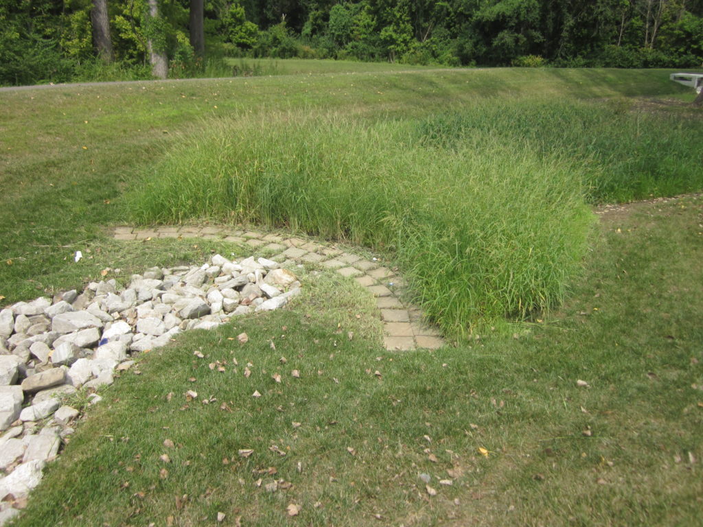
At the discretion of the design engineer, bioretention basins with point discharges and tributary watershed areas less than 2.5 acres may be managed by a stabilized rock outfall and a heavy stand of vegetation (such as switch grass or cord grass). Incoming pipes should be designed such that incoming velocities are minimized. A minimum 10′ long stabilized rock blanket/rip rap is recommended at the pipe outfall (similar to MSD Standard Detail 61) or an alternative pervious segmented hard surface. As a rule of thumb, the vegetated buffer should be minimum 3-10′ wide prior to the transition zone. An illustrative example is provided below:
Figure 3: Vegetated Cordgrass Buffer, downstream of flared end section and rock blanket
The ground within the Pretreatment Zone may be established with native grasses, turf grass, or a hardened surface at the discretion of the design engineer.
Transition Zone
A vegetated transition between the pretreatment zone and the filter bed should be configured in a manner that would transfer and distribute flow to the filter bed. This also includes all areas within the basin not occupied by the bioretention filter bed. Native grasses should be plug planted or applied via a “wet” native prairie seed mix for grades less than 2%. Either native prairie grasses or turf grass sod may be used for grades greater than 2%. Regardless of slope, the areas draining towards the filter bed should be graded for positive drainage and configured to minimize the potential for scour at the filter bed.
The MSD Landscape Guide provides recommendations for species and methods for establishing native vegetation via seeding or plugging.
Treatment Zone
The treatment zone consists of the bioretention filter bed, native plants, underdrain system, and outlet control structure. Maximum ponding depths are 18″ for WQv, 36″ for CPv, and up to 5.5′ for the 2yr and 100yr-24 hour Qp events. Storage for each event may be counted within the void space of the bioretention soil media and the above grade surface ponding areas within the basin. The size of the bioretention filter media shall be done in accordance with MSD bioretention criteria illustrated here in the BMP Toolbox.
Bioretention filter media and plantings should not be planted until the upstream watershed areas are fully stabilized.
CPv and Qp Routing
Generally CPv and WQv are nested and provided beneath the lowest control opening on the outlet control structure. All or portions of the of the CPv may be routed through the 2yr opening of the control structure as long as the necessary storage is provided within the basin to allow for the site’s required CPv release rate to be met.
2yr and 100yr-24 hour flood routing is performed in accordance with MSD Rules and Regulations. The starting water surface elevation may begin at the bottom of the bioretention soil media, assuming storage within the media (35-40% void space) and the open space above ground within the surface basin and forebay. The underdrain does not need to be taken into account in the routing since the filter bed is typically designed to drain within a longer time period than what is normally necessary to obtain 2yr and 100yr flow attenuation.
100yr-24 hour low flow blocked calculations shall be performed assuming that the lowest orifice and any intermediate flow openings are fully blocked and water is ponded to the overflow structure’s sill for the initial routing condition unless directed otherwise by the District. Maximum ponding elevation within the basin shall not exceed 5.5′ and one foot of freeboard is required.
CN modification cannot be claimed with nested bioretention.
Details
The following details are intended to provide conceptual illustration of MSD’s guidance on nested bioretention design, and are not a substitute for site specific drawings and details.
Nested Bioretention with a Forebay pretreatment option
Nested Bioretention with a vegetated buffer pretreatment option

